crumble

Joined: Sep 09, 2008
Posts: 3158
Guildford England


|

Posted on Aug 14 2009 01:56 PM
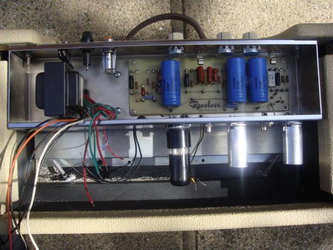
My Hoffman 6G15 board finally arrived this morning. It won't be alive and kicking for a while yet but here's a few pictures that might interest some of you. Just need an output transformer and few other bits and then it goes off to qualified engineer.


|
Hoosier-Hodad

Joined: Jun 09, 2009
Posts: 135
San Jose, CA.
|
Posted on Aug 14 2009 05:51 PM
I really like the layout and components on these boards. I might get one of these myself.
Here's a diagram:
http://www.el34world.com/Hoffman/images/fendrev.gif
|
LHR

Joined: Aug 23, 2006
Posts: 2123
The jungle


|
Posted on Aug 15 2009 12:11 AM
My reverb unit uses this exact same turret board. I have never seen it, though. Looks pretty nice!
— SSIV
|
El-Salvaje

Joined: May 22, 2007
Posts: 73
berlin germany
|
Posted on Aug 15 2009 02:12 AM
The beauty and magic mystery of well done work.
xxx
|
Thunderhead
Joined: Apr 11, 2009
Posts: 201
|
Posted on Aug 15 2009 04:18 AM
Looks Great, Very Tidy Work. 
— www.myspace.com/thethunderheads
|
crumble
Joined: Sep 09, 2008
Posts: 3158
Guildford England
|
Posted on Sep 05 2013 08:10 AM
Gosh time does fly. When I gave up trying to be a surf band I lost interest in this project for a few years.
Presently at the stage of wiring, it would be of great interest to see how other Hoffman 6G15 builders accomplished their task. If you have a completed Hoffman stand alone reverb unit with this specification turret board please upload photos to this thread. Thank you.
Currently the only decent Hoffman 6G15 photos I can find with Google are the ones I posted at the beginning of this thread.
Greatly Appreciated.

|
BJB

Joined: Jul 28, 2008
Posts: 413


|
Posted on Sep 06 2013 02:17 PM
I've installed Hoffman boards for other people and I have to say I am not a fan. I have issues with this board but the #1 concern is the power supply capacitor that is located directly over the hot reverb driver tube. This is a huge no-no because exposing electrolytic capacitors to heat reduces their life! The originals had the caps on the other side of the chassis, away from the heat. But who knows, some people seem to be able to get away with breaking the rules. Good luck!
— If it ain't broke, fix it until it is.
|
crumble
Joined: Sep 09, 2008
Posts: 3158
Guildford England
|
Posted on Sep 06 2013 05:36 PM
BJB wrote:
I've installed Hoffman boards for other people and I have to say I am not a fan. I have issues with this board but the #1 concern is the power supply capacitor that is located directly over the hot reverb driver tube. This is a huge no-no because exposing electrolytic capacitors to heat reduces their life! The originals had the caps on the other side of the chassis, away from the heat. But who knows, some people seem to be able to get away with breaking the rules. Good luck!
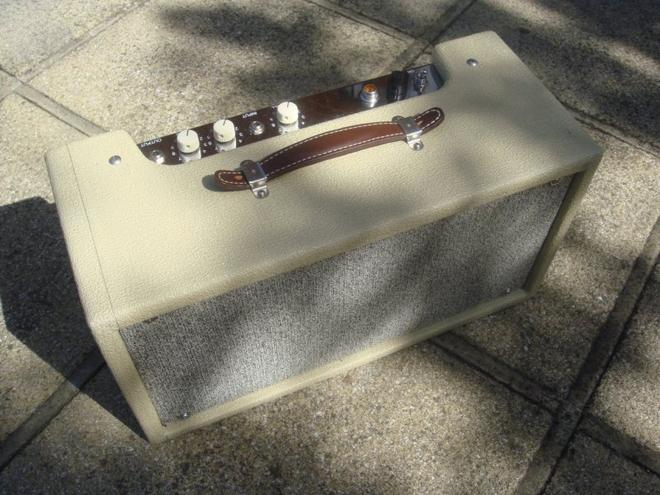
This is my third chassis. The second one I had made a 1/2" inch deeper to allow for more component space, the wood plank I used to build the box was an inch wider than standard so there was plenty of room behind for the output transformer. Due to the high price of nickel plating the steel chassis + face plate hassles I finally opt for a factory built chrome job.
I agree that the capacitor is a bit too close for comfort.
You pays your money and takes your pick, as they say!
Last edited: Sep 06, 2013 17:41:13
|
BJB
Joined: Jul 28, 2008
Posts: 413
|
Posted on Sep 06 2013 05:59 PM
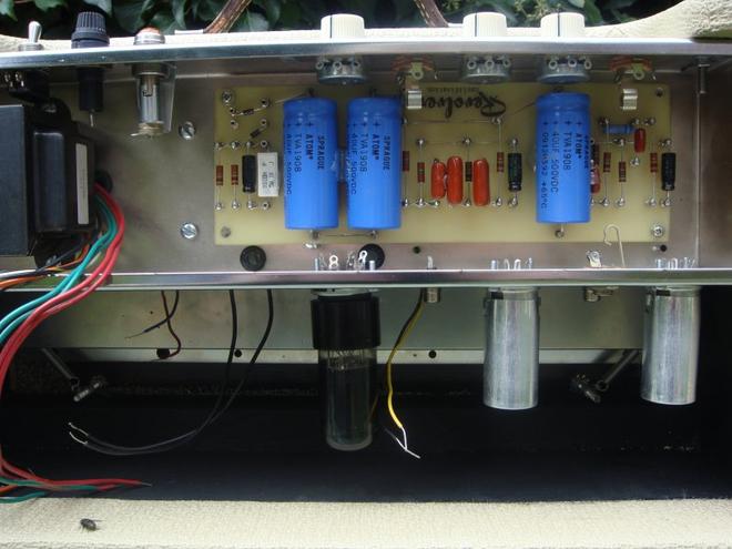
These reverb units are great projects! I bought a Fender reissue from a friend for $200 (he was quitting the music biz), then wired it up myself using parts scavenged from various electronics swap meets and surplus yards. Here's a picture I took back in 1998 when I was pretty much at the stage you are now:
image
— If it ain't broke, fix it until it is.
|
crumble
Joined: Sep 09, 2008
Posts: 3158
Guildford England
|
Posted on Sep 06 2013 06:06 PM
Perhaps modern day capacitors are more hardy. I've read Japanese caps found in high end pc motherboards and PSU's (85C or 105C) should last many times that of a standard cap. What's the life span of a 1960s spec cap - 10 years max? Hopefully the greater part of the heat stays outside the chassis.
|
BJB
Joined: Jul 28, 2008
Posts: 413
|
Posted on Sep 09 2013 05:34 PM
crumble wrote:
Perhaps modern day capacitors are more hardy. I've read Japanese caps found in high end pc motherboards and PSU's (85C or 105C) should last many times that of a standard cap. What's the life span of a 1960s spec cap - 10 years max? Hopefully the greater part of the heat stays outside the chassis.
Some PC caps do have a high temperature rating, but yours are rated at only 65C. Also, computers generally have a fan to keep the components cool but even then, motherboard electrolytics will still explode. This is why some motherboards use tantalum caps instead of electrolytic.
Anyway, there is an equation for capacitor lifetime vs. temperature and it turns out that every time you add 10C to the operating temperature, you cut the lifetime in half:
http://www.illinoiscapacitor.com/tech-center/life-calculators.aspx
Since room temperature is 25C and the max temp is 65C, you only have a 40C margin to play with. But since the cap is located directly above a tube, and heat rises, you have something less than this 40C margin. However, if you really did have 105C caps, then there would be an 80C margin, which gives you an extra 16x worth of lifetime.
Like I said earlier, I am familiar with the Hoffman boards and I am not a fan. The design is just plain bad, and the choice of components only makes their bad design even worse. Just so you know, you can get an Illinois 47uF/500V cap from Antique Electronics that's rated at 85C and it costs about $6. You pays your money and takes your pick, as they say!
— If it ain't broke, fix it until it is.
|
Hammond101

Joined: Feb 22, 2013
Posts: 342
SoCal USA
|
Posted on Sep 09 2013 06:13 PM
I wouldn't be too concerned over temps inside the chassis. Yes, Fender mounted the filters outboard in a doghouse cover similar to a BF amp however after a long period of use, a hour or two, the whole chassis will heat soak inside those small cabs. I'd expect at least 10-15 years out of the caps pictured. I don't think the tube temps are any more or less an issue no matter where the caps are located.
I prefer F & T caps at present. High quality and their smaller physical size puts them in places only lesser brands would fit in the past.
— Keep it Drippy Brothers and Sisters!
|
BJB
Joined: Jul 28, 2008
Posts: 413
|
Posted on Sep 10 2013 01:36 PM
I have some good news about this board. It turns out that you installed it backwards!
I noticed that the components associated with the driver tube and power supply diodes are on the upper right corner of the chassis. Those components should be left side, close to the driver tube and power transformer. This means that you have installed the board wrong. But this is good because now that one capacitor won't be cooked by the driver tube.
When you get a chance, remove the board, reinstall it correctly, and show us some pictures so we can see how this thing is supposed to look.
— If it ain't broke, fix it until it is.
|
crumble
Joined: Sep 09, 2008
Posts: 3158
Guildford England
|
Posted on Sep 10 2013 02:22 PM
That's one of the reasons I needed a photo of a completed Hoffman 6G15 project!
This is the only photo of the board on the Hoffman site(s). You'd think this is the way to install it but looking at the potentiometer layout it is upside down, plus some writing at the top is upside down also.
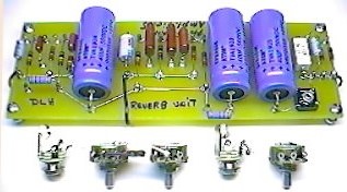
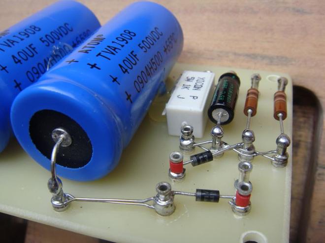
If you look to the bottom right of the board there is a BR310 bridge rectifier unit, mine doesn't have that and it's confusing the hell out of me.
Last edited: Sep 10, 2013 17:11:48
|
crumble
Joined: Sep 09, 2008
Posts: 3158
Guildford England
|
Posted on Sep 10 2013 03:08 PM
There are no specific product instructions only generic amp information written from the point of view of a qualified electronics engineer - Well sort of.
I bought the board as ready made hoping it would include detailed instructions with photos but he just sent a printout of Hoffman website hieroglyphics. I'm working through this now and a lot of the stuff I thought i'd never be able to understand only a few weeks ago i'm now starting to understand. I'm just a few grey areas away from hookup.
|
cambeezy

Joined: Jun 26, 2007
Posts: 399
Cleveland, Ohio
|
Posted on Sep 10 2013 04:46 PM
crumble, I know what you're going through. Schematics are hieroglyphics to me too. I'd post the Triode diagram (for dummies like me) but components are in diff places and wouldn't be much help. Anyway, sounds like you're getting it sorted out!
BJB, good eye!
|
crumble
Joined: Sep 09, 2008
Posts: 3158
Guildford England
|
Posted on Sep 10 2013 05:06 PM
Yes well spotted. I'll spin her round and take a picture tomorrow.
Last edited: Sep 10, 2013 17:10:36
|
BJB
Joined: Jul 28, 2008
Posts: 413
|
Posted on Sep 10 2013 05:13 PM
I'm sure this is frustrating for you but you should be proud of the progress you are making!
Instead of the bridge rectifier, your version of the board has two diodes that are connected (more or less) in series as a half-wave rectifier. The two red wires from the power transformer are meant to be attached to those two red turrets near the corner of the board, next to the two big blue capacitors. The original Fender reverb unit also used a half-wave rectifier but the reissues and everyone else uses a full-wave bridge. The advantage of the full-wave is that there is less power supply ripple, which makes life easier on the power supply capacitors:

In the old days, diodes were expensive and it was cheaper to go with a half-wave rectifier and use bigger power supply capacitors than add the extra diodes required for full-wave.
I also used a full-wave rectifier but I did mine using four individual diodes. That tiny brown board next to the cap board is dedicated entirely to these four diodes! It would have been possible to add two diodes to your board and convert it to full-wave, but diodes cost nearly 10 cents each and that seems to be more cost than the company was willing to put into building this board.
— If it ain't broke, fix it until it is.
Last edited: Sep 10, 2013 17:14:20
|
crumble
Joined: Sep 09, 2008
Posts: 3158
Guildford England
|
Posted on Sep 10 2013 05:51 PM
That's really helpful thanks. I have been made aware that my MoJo 779 PT needs a full wave rectifier but I started wondering if the board was designed for a separately mounted rectifier and the diodes were just extra filters. At the moment I can't source the exact square bridge 1000v 3a rectifier Hoffman uses here in the uk. But as soon as I can get one it'll be easy to pop a turret post and attach on.
|
crumble
Joined: Sep 09, 2008
Posts: 3158
Guildford England
|
Posted on Sep 11 2013 08:13 AM
Haha! I don't think this will be up to your standards BJB. I shouldn't laugh because all the mount holes are out of alignment and I can only get two screws in! 
Oh well, assume lotus position, breathe..
|


